Settings for external I/O interface of the controller can be changed.
The settings can be changed for input and output of various data using the controller Ethernet port.
|

|
If any incorrect settings are made the system as well as other network equipment may not work properly. For details of the setting value, consult the system or network administrator.
|

Acquires the network configuration information (IP address/Subnet Mask/Default Gateway) from the BOOTP server at the controller activation.
(Default: Disabled)
The received network information is reflected in the global settings. When receiving the information from the BOOTP server fails at the next activation, the stored configuration is used for activation.
Set the network configuration information (IP address/Subnet Mask/Default Gateway).
Specify the desired IP address for the controller if necessary.
- IP Address (default setting: 192.168.0.10)
- Subnet Mask (default setting: 255.255.255.0)
- Default Gateway (default setting: 0.0.0.0)
|

|
Send a ping command to the device to be connected (IP address) from [Check Connection] to check the connection with the controller. If the message “Failed to verify connection with the connected device.” appears, check the IP address settings and LAN cable.
|
Input the port number to use for non-procedural communication (command/result output). (Default: 8600)
Select the delimiter for the Ethernet communication from [CR] (default) or [CR+LF].
Enter the port number to use when communicating with the PC program.
(default: 8601)
Displays the MAC address for the controller.
Select the frame size (4 KB) to be used when using jumbo frames (default setting: Disable).
|
|
- If the settings are changed, it is necessary to restart the controller.
- This setting is only enabled on the Ethernet port on the controller. The communication expansion unit (CB-NEC20E/NEP20E/NPN20E/NPN20EA) is not supported.
- To use jumbo frames, all devices on the network must support jumbo frames.
|
Configure the following settings to communicate with external devices in the RS-232C non-procedural mode:
- Baud Rate
- Stop Bit
- Parity Bit
- Flow Control
- Delimiter
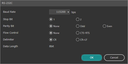
Select the “Baud Rate” (bps) from the following options:
- 9600/19200/38400/57600/115200 (default)/230400
The settings can be changed to use the controller as an FTP client or server.
|
|
When [FTP] is selected as the image loader and SFTP transfer is enabled, only ASCII characters can be used as file and folder names.
|
The controller can access an FTP server (PC or a network-enabled hard disk with FTP server functionality) via Ethernet interface using its FTP client function.
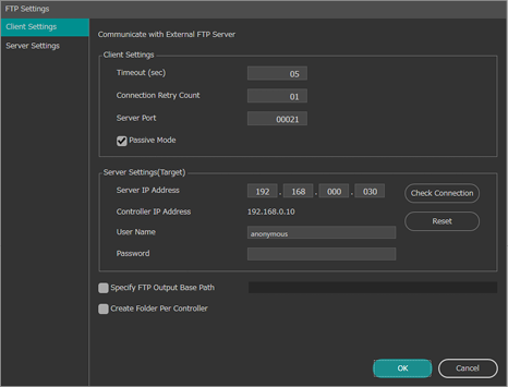
Enter the timeout period in seconds to wait for a response from the FTP server during data output.
(default: 5 seconds)
Enter the number of attempts to log in when connection to the FTP server fails.
(default: 1 second)
Enter the port number of the FTP server used for control.
(default: 21)
Check this option when using FTP in passive mode.
(default: ON (passive mode))
Check this option when using SFTP (SSH File Transfer Protocol).
(default: OFF)
|
|
When using SFTP, it is recommended to disable the FTP server function of the controller for greater security.
|
Specify the IP address of the FTP server.
(default: 192.168.0.30)
Shows the IP address of the controller.
Specify the login user name of the FTP server.
Specify the login password of the FTP server.
|
|
- Send a ping command to the device to be connected (IP address) from [Check Connection] to check the connection with the controller. If the message “Failed to verify connection with the connected device.” appears, check the IP address settings and LAN cable.
- Press [Reset] to restore [Server Settings (Target)] to their default settings.
|
Ticking this box will allow specification of the base path for the FTP output. The base path specified here will be applied to all FTP outputs including result and image outputs.
If this box is ticked, a folder with the controller’s IP address as its name will be created and output via FTP when it is done.
This option can separate the data when outputting data from multiple controllers to the same FTP server.
The controller functions as an FTP server.
The SD memory card in the controller can be accessed from an external FTP client via Ethernet.
|
|
Available users are ‘admin’ (Administrator), ‘operator’ (Operator) and ‘anonymous’.
(‘operator’ and ‘anonymous’ are read-only users.)
|
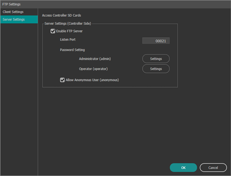
To take effect the [Enable FTP Server] setting change, the controller must be restarted.
Enter the port number to be opened for the FTP client.
(default: 21)
To take effect the [Listen Port] setting change, the controller must be restarted.
Set an administrator (admin) and operator (operator) password.
|
|
The characters that can be used are alphanumeric characters and symbols that are between 4 and 32 characters. Alphabetic letters are case sensitive.
|
Select this check box to permit access from anonymous users (user name is ‘anonymous’).
(Default: Disabled)
When accessed by an anonymous user, operation of files and folders on the controller, and transfer of files to the controller is not allowed (file reading only is allowed).
Settings for data input/output through the controller’s external terminals (parallel I/O connector and terminal block) can be changed.
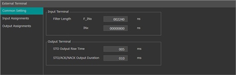
- Filter length: F_INx (ns)
To eliminate noise signals, specify the time for signals to be treated as noise between 40 and 153600 ns (default setting: 2240 ns).
To eliminate noisy signals, specify the time for signals to be treated as noise between 40 and 81264600 ns (default setting: 800 ns).
- STO Output Rise Time (ms)
Set the length of time from when the data is ready for output to when the STO starts up within the range of 1 to 500 (ms). (Default: 5 ms)
- STO/ACK/NACK Output Duration (ms)
Set the length of time from when the STO rises to when the STO falls within the range of 1 to 500 (ms). (Default: 10 ms)
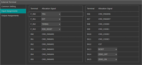
Select the signal to be assigned to the input terminals.
|
|
The same [Allocation Signal] cannot be set to multiple [Terminal].
If [Allocation Signal] is duplicated, the field will be displayed in orange.
|
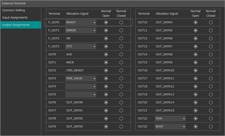
Select the output format and signal to be assigned to the output terminals.
- Normally open : Produces output in normal mode.
- Normally closed : Produces output inverted from normally open-mode output.
|
|
The same [Allocation Signal] cannot be set to multiple [Terminal].
If [Allocation Signal] is duplicated, the field will be displayed in orange.
|
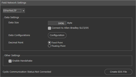
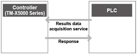
EtherNet/IP is an industrial protocol for communicating with a programmable logic controller (PLC) via the Ethernet port on the controller or an EtherNet/IP Unit (CB-NEP20E: Optional).
Through EtherNet/IP, data input and output between the controller and the PLC, as well as command issuance from the PLC to the controller are possible.
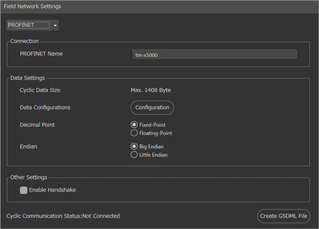
PROFINET is an industrial protocol for communicating with a programmable logic controller (PLC) via the Ethernet port on the controller or a PROFINET Unit (CB-NPN20E/CB-NPN20EA: Optional).
Through PROFINET, data input and output between the controller and the PLC, as well as command issuance from the PLC to the controller are possible.
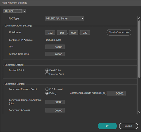
PLC-Link is a communication mode where data transmission is performed between the controller and the data memory of the PLC (programmable logic controller) via the Ethernet interface on the controller. In addition to measurement data output, command execution is also available through the PLC-Link.
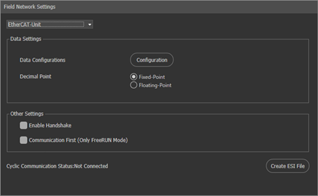
EtherCAT is an industrial protocol for communicating with a programmable logic controller (PLC) via an EtherCAT Unit (CB-NEC20E: Optional).
By using EtherCAT, data input and output between the controller and the PLC, as well as command issuance from the PLC to the controller are possible.
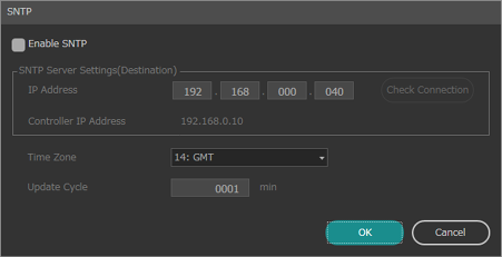
SNTP (Simple Network Time Protocol) is a communications protocol that is used to synchronize computer clocks on a network.
Enabling SNTP on a controller installed on the network that can communicate via SNTP allows accurate time to be obtained by connecting to a SNTP server and regularly synchronizing the time of the clock built into the controller.
|
|
If an error occurs while synchronizing the time with the SNTP server, an error message will appear on the lower left of the screen. This error message will continue to be displayed until synchronization is successful at the next update cycle or SNTP settings are reconfigured.
|
Selects whether to connect to the SNTP server and synchronize the time. Check this box to enable.
Set the IP address for the SNTP server.
(default: 192.168.000.040)
|
|
Use [Check Connection] to check whether communication with the destination is possible.
|
Select the time zone of the SNTP server to obtain the time from.
(default: 14: GMT)
Main time zones
|
4: GMT
|
-8:00
|
Pacific Standard Time
|
|
6: GMT
|
-6:00
|
Central Standard Time, Mexico City, Central America
|
|
9: GMT
|
-4:00
|
Atlantic Standard Time
|
|
11: GMT
|
-3:00
|
Brasilia
|
|
12: GMT
|
-2:00
|
Central Atlantic Time
|
|
14: GMT
|
|
London, Coordinated Universal Time
|
|
15: GMT
|
+1:00
|
Berlin, Brussels, Rome, Paris, Bern
|
|
16: GMT
|
+2:00
|
Athens, Jerusalem
|
|
17: GMT
|
+3:00
|
Kuwait
|
|
19: GMT
|
+4:00
|
Moscow
|
|
22: GMT
|
+5:30
|
New Delhi
|
|
26: GMT
|
+7:00
|
Bangkok
|
|
27: GMT
|
+8:00
|
Kuala Lumpur, Singapore, Taipei, Beijing
|
|
28: GMT
|
+9:00
|
Japan, Seoul
|
|
30: GMT
|
+10:00
|
Canberra and Sydney
|
Set the cycle to obtain the time from the SNTP server.
(default: 1)
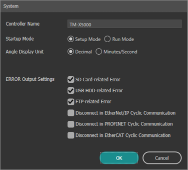
The following settings can be configured:
- Controller Name
- Startup Mode (default: Setup Mode)
- Angle Display Unit (default setting: Decimal)
- ERROR Output Settings
| - A text string of up to 32 characters can be entered for the controller name.
- Decimal is set for the angle tolerance even when [Minutes/Second] is set for [Angle Display Unit]. Additionally, the [Measurement Result Output] function sends minutes as the first and second decimal points, and seconds as the third and fourth decimal points.
For example, 12°34′56″ is saved in a cell as 12.3456. |
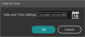
Use the following procedure to set the controllers built in clock.
|
|
The TW command can also be used to synchronize the time.
|
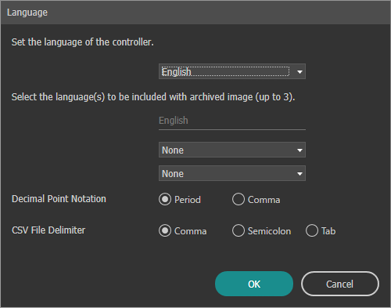
The language for the following items can be changed:
- Language displayed on the controller screen.
- Language contained in archived images.
- Decimal point notation.
- Delimiter characters in CSV files.
|
|
Archived images can contain tool names in multiple languages. Including the tool name in the desired display language in the simulator enables the tool name to be displayed in that language.
If the archived image does not include the tool name in the applicable language, the tool name is displayed with the default name.
|
The controller can be restarted without turning the power off.
Set a password to restrict editing of Programs.
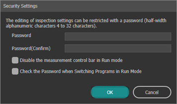
|
|
The characters that can be used are alphanumeric characters that are between 4 and 32 characters. Alphabetic letters are case sensitive.
|
Hardware, available memory resources, and other information about the system can be checked.
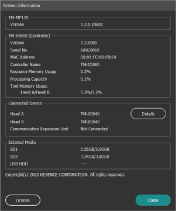
|
|
The menu displayed above (indicated by (A)) may be one of the following according to the settings in  “Field network”: “Field network”:
- (None)
- EtherNet/IP Memory Monitor
- PROFINET Memory Monitor
- PLC-Link Memory Monitor
- EtherCAT Memory Monitor
|
The connection status of signals input and output via the I/O connector (parallel I/O interface and terminal block interface) of the controller can be checked.
When proper signal transmission between the connected devices fails, this feature is very useful as the connection status of the terminal in the controller can be verified while the controller and external equipment are connected.
|
|
- [I/O Monitor] can be used in either Setup mode or Run mode.
- When [External Trigger] is set, the [Trigger] button is displayed in [Run] mode.
|
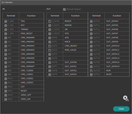
With this item selected, a specific output terminal can be forcefully set to ON. After selecting this item, place a check mark on the box of the terminal to set to ON.
|
|
[Manual Output] can be used only in [Setup] mode.
|
Indicates the connection status of each terminal. A check mark is placed on the terminal in the ON (short circuit) status. The status is updated in real time in response to input and output signals.
The communication status of signals input and output via the RS-232C port or Ethernet connector on the controller can be checked.
When proper data transmission between the connected devices fails, this feature is very useful as the communication content can be verified while the controller and external equipment are connected.
|
|
[RS-232C Monitor] and [Ethernet Monitor] can be used in either [Setup] mode or [Run] mode.
|
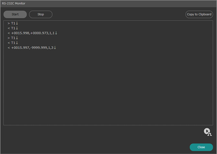
The status is updated in real time in response to input and output commands.
- [<] is given to the head of the output data from the controller while [>] is given to the head of the input data to the controller.
- Characters other than ASCII code are displayed in hexadecimal.
Start or stop the display of communication details.
Copy the communications log to the clipboard.
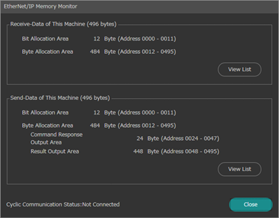
The communications status for input and output signals during EtherNet/IP communications via the controller or the EtherNet/IP unit (CB-NEP20E: Optional) can be checked.
When proper data transmission between the connected devices fails, this feature is very useful as the communication content can be verified while the controller and external equipment are connected.
|
|
- If [EtherNet/IP] or [EtherNet/IP-Unit] is selected for “Field network”, [EtherNet/IP Memory Monitor] is available.
- When [Cyclic Communication Status] is [Not Connected], monitoring is not possible. Use the monitor after establishing the EtherNet/IP connection.
- The [EtherNet/IP Memory Monitor] function can be used in either [Setup] mode or [Run] mode.
- When [External Trigger] is set, the [Trigger] button is displayed in [Run] mode.
|
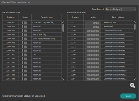
Select the values to be monitored from [Data Format] on the upper right of the screen.
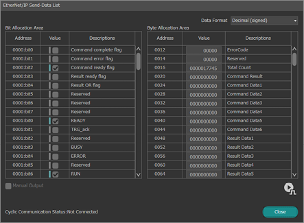
- Select the values to be monitored from [Data Format] on the upper right of the screen.
- Select [Manual Output] to manually change the value for the selected address and confirm the change on the PLC side.
|
|
[Manual Output] can be used only in [Setup] mode.
|
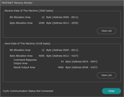
The communications status for input and output signals during PROFINET communications via the controller or the PROFINET unit (CB-NPN20E/CB-NPN20EA: Optional) can be checked.
When proper data transmission between the connected devices fails, this feature is very useful as the communication content can be verified while the controller and external equipment are connected.
|
|
- If [PROFINET] or [PROFINET-Unit] is selected for “Field network”, [PROFINET Memory Monitor] is available.
- When [Cyclic Communication Status: ] is [Not Connected], monitoring is not possible. Use the monitor after establishing a PROFINET connection.
- The [PROFINET Memory Monitor] function can be used in either [Setup] mode or [Run] mode.
- When [External Trigger] is set, the [Trigger] button is displayed in [Run] mode.
|
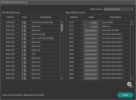
Select the values to be monitored from [Data Format] on the upper right of the screen.
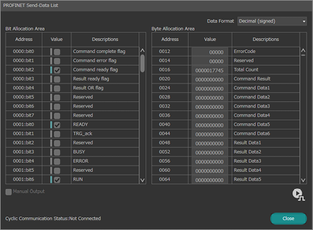
- Select the values to be monitored from [Data Format] on the upper right of the screen.
- Select [Manual Output] to manually change the value for the selected address and confirm the change on the PLC side.
|
|
[Manual Output] can be used only in [Setup] mode.
|
Check the system’s PLC-Link I/O signal communication status with this function.
When proper data transmission between the connected devices fails, this feature is very useful as the communication content can be verified while the controller and external equipment are connected.
|
|
- Use of [PLC-Link Memory Monitor] is available only when [PLC-Link] is selected in “Field network”.
- When [Connection Status] is [Not Connected], monitoring is not possible. Use the monitor after establishing the PLC-link connection.
- The [PLC-Link Memory Monitor] function can be used in either [Setup] mode or [Run] mode.
- When [External Trigger] is set, the [Trigger] button is displayed in [Run] mode.
|
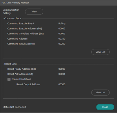
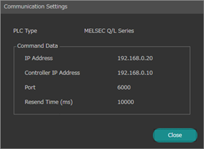
Displays the status of communications with the PLC.
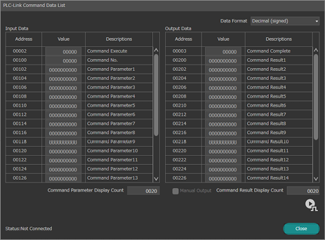
- Select the values to be monitored from [Data Format] on the upper right of the screen.
- The number of command parameters displayed can be changed in [Command Parameter Display Count].
- Select [Manual Output] to manually change the value for the selected address and confirm the change on the PLC side.
- The number of command results displayed can be changed in [Command Result Display Count].
|
|
[Manual Output] can be used only in [Setup] mode.
|
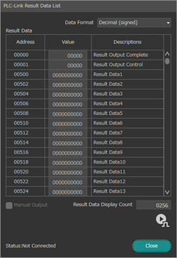
- Select the values to be monitored from [Data Format] on the upper right of the screen.
- Select [Manual Output] to manually change the value for the selected address and confirm the change on the PLC side.
- The number of items of results data displayed can be changed in [Result Data Display Count].
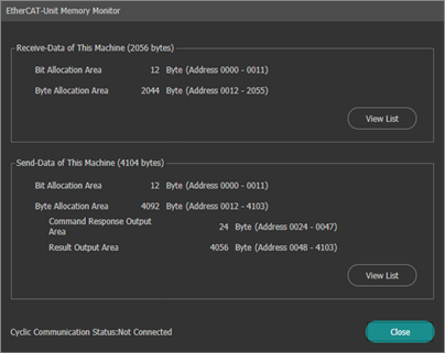
The communications status for input and output signals during EtherCAT communications via an EtherCAT unit (CB-NEC20E: Optional) can be checked.
When proper data transmission between the connected devices fails, this feature is very useful as the communication content can be verified while the controller and external equipment are connected.
|
|
- Use of [EtherCAT Memory Monitor] is available only when [EtherCAT-Unit] is selected in “Field network”.
- When [Cyclic Communication Status] is [Not Connected], monitoring is not possible. Use the monitor after establishing the EtherCAT connection.
- The [EtherCAT Memory Monitor] function can be used in either [Setup] mode or [Run] mode.
- When [External Trigger] is set, the [Trigger] button is displayed in [Run] mode.
|

Select the values to be monitored from [Data Format] on the upper right of the screen.
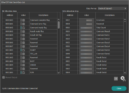
- Select the values to be monitored from [Data Format] on the upper right of the screen.
- Select [Manual Output] to manually change the value for the selected address and confirm the change on the PLC side.
|
|
[Manual Output] can be used only in [Setup] mode.
|
Check a trend graph based on the measurement results and output results in CSV format.
“Statistics”
|
|
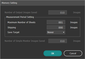
[Memory Setting] can only be set in [Setup] mode.
|
Set the number of saved images to be output from the controller.
These settings are only enabled if [Hold Mode] is set to [ON].
Set the maximum number of output images to save, number of images to omit, and images to be saved during the measurement period.
Sets the number of saved images to be displayed on the Simple Monitor.
|
|
Images are saved in the controller’s internal memory according to the following settings:
- Number of image buffers in [Head Settings]
- [Image Output]/[Simple Monitor Image Output] for [Output Condition]
- [Store Condition] for [Archived Image Settings]
If [Output Condition] for [Image Output]/[Simple Monitor Image Output] and [Store Condition] for [Archived Image Settings] are the same, the remaining areas excluding the image buffer are assigned to the “Image Output,” “Simple Monitor Image Output,” and “Archived Images” areas.
(One image is used for both image output and image archive.)
|
Image Buffer
|
Image Output/
Simple Monitor Image Output/
Archived Image
(Number of output images saved/
Number of simple monitor images saved)
|
If [Output Condition] for [Image Output]/[Simple Monitor Image Output] and [Store Condition] for [Archived Image Settings] are not the same, the remaining areas assigned to “Image Buffer” and “Image Output”/“Simple Monitor Image Output” are assigned to the “Archived Images” area.
(Images are stored as archived images in addition to being output.)
|
Image Buffer
|
Image output/
Simple monitor image output
(Number of output images saved/Number of simple monitor images saved)
|
Archived Image
|
|
Set the conditions and period to store images as archived images.
“Archived Image Settings”
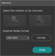
Remove safely the SD card 2 inserted in the controller or the USB HDD connected to the controller. In addition, format SD Card 2 or USB HDD.
|
|
- Make sure to always follow the on-screen instructions to protect the SD memory card and the data it contains.
- If the SD memory card or USB HDD is removed using a procedure other than that specified, or if power is turned off when the card is being accessed, any writing task will stop resulting in a possible loss of data or damage to the SD memory card.
|
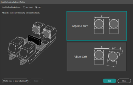
This function adjusts the positional relationship between heads when measuring an object with two heads that cannot be measured by one head (such as the diameter of a large object).
Adjust the positional relationship by following the on-screen instructions.
Use the object for adjustment for which the size is known to make the adjustments.
|
|
Clicking [Initialize] deletes the head-to-head adjustment value.
|
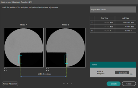
The positional relationship between heads can be adjusted when [Head-to-head Adjustment Setting] is configured.
This function assumes that an object of known size is regularly used for adjustment (when necessary) prior to operation.
|
|
By using [Manual Adjustment], the positional relationship between heads can be adjusted manually.
|