Chapter 2 Installing the TM-X5000 Series
Installing the Head
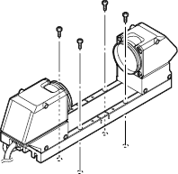
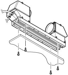
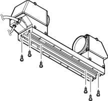
The sensor head can be installed according to the specific environment and target.
This section explains the method to use the supplied transmitter/receiver base.
Caution for installation
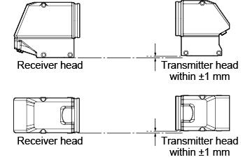
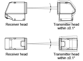
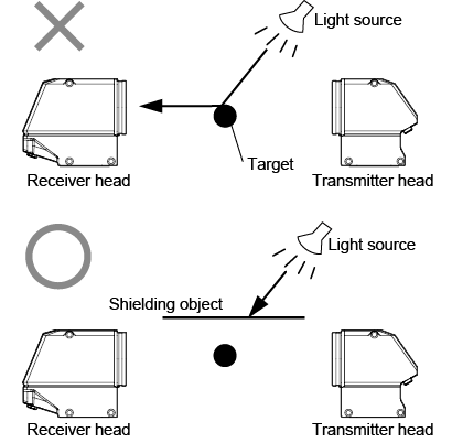
When installing the sensor heads, make sure the following conditions are met.


Installations for specific environments
Installation method

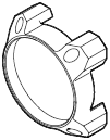
Attaching the Protective Cover
Attaching the protective cover (sold separately) reduces the amount of dust that adheres to the glass covers on the transmitter and receiver.
This section describes how to attach the protective cover and handling precautions.
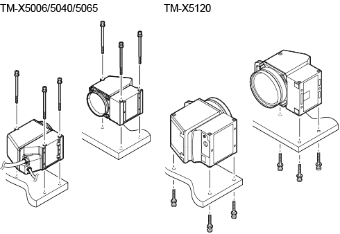
Checking the Package Contents
OP-88575 (for TM-X5040)
- Protective cover unit x 2
- M3 x L8 hexagon socket bolt x 8
OP-88576 (for TM-X5065)
- Protective cover unit x 2
- M3 x L8 hexagon socket bolt x 8
OP-88775 (for TM-X5120)
- Protective cover unit x 2
- M4 x L50 hexagon socket bolt x 8
Installation method
- Blow any grime or dust off the glass with clean air.
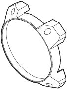
- Attach the protective cover to the transmitter or receiver on the head with the correct orientation.

|
|
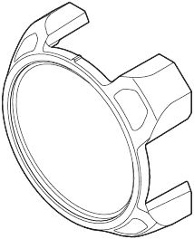
For TM-X5120, align the pins (x2) on the bottom of the protective cover with the slot on the head to install the protective cover. |
- Secure with the four included hexagon screws.
Tightening torque: 0.62 N•m or lower
Maintenance
If any grime or dust has adhered to the glass, blow it off with clean air. If the soiling is particularly bad, wipe the glass surface gently using a soft cloth moistened with alcohol (IPA, ethanol, or the like).
Installing the Controller
Mount the controller to the DIN rail or use the screw from holes on the bottom to secure it securely.
|
|
|
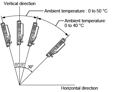
Cautions on the installation direction of the controller
The controller should be installed in the direction of the circled figure below. Do not install it in any other direction.

Precautions on cooling of the controller at the installation location
- For ventilation, secure free space of 50 mm or more above the controller and 50 mm or more for both sides. In addition, to ensure the safe connection of the cable, secure 90 mm or more of free space in front of the connector panel of the controller.
- When two or more controllers are installed side by side, secure free space of 50 mm or more between controllers, and 50mm or more on top of both controllers.
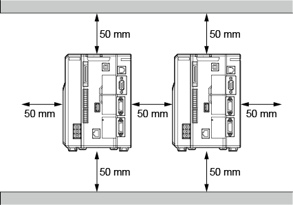
*If spaces of 50 mm or more are ensured of even on the underside orientations by DIN rail mounting, etc., then the units can be used at higher than ambient temperatures.
|
|
|
Installing the Controller
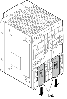
Mounting the controller to the DIN rail
The controller is designed to be mounted on a DIN rail. Pull the tab on the bottom in the direction of the arrow to mount or dismount the controller.
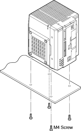
Mounting to the bottom panel
|
|
Mount the controller in a stable location that is free from vibration. |
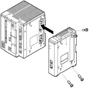
Installing the Communication expansion unit
|
|
|

Optional Communication Units Available:
(EtherCAT: CB-NEC20E, EtherNet/IP: CB-NEP20E, PROFINET: CB-NPN20E)
Remove the connector protection sticker from the communication expansion unit connector on the right side of the controller and install the communication expansion unit.
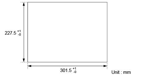
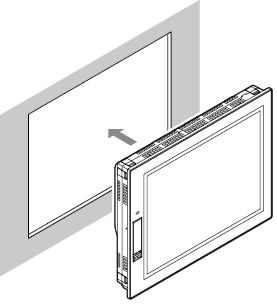
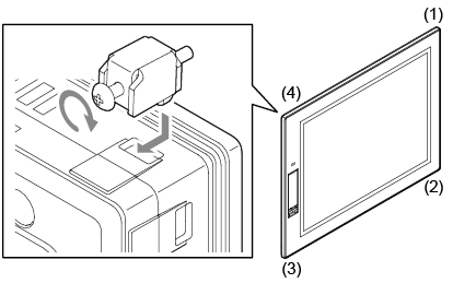
Installing the Dedicated Monitor for TM-X
Description of how to mount the front side of the dedicated monitor for TM-X.
Mounting fixtures (supplied parts) are required for mounting.
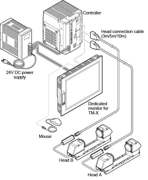
Wiring
|
|
|
|
|
|

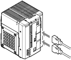
- Connect the head connection cable to the head port of the controller.
If connecting only a single head, connect it to the head A port.
Check that a clicking sound is heard, confirming that the cables are securely fixed. When removing the cables, pull them out while pressing the buttons on both sides of the connector.
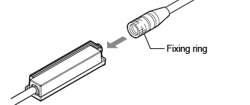
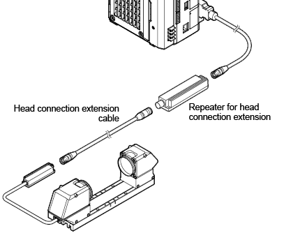
- Connect the cable connector between the transmitter head and receiver head.
|
|
The connection cable between the transmitter head and the receiver head can be extended up to 3 m using the transmitter-to-receiver cable. |
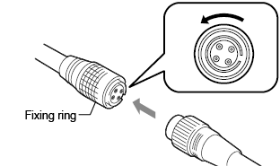
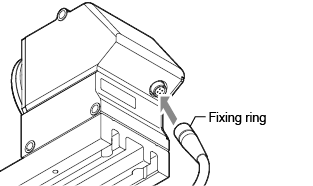
- Connect the head to the head connection cable.
Align the connector and insert, then turn the fixing ring to fix.
|
|
|
|
|
Plug in the connector making sure its orientation is correct. Inserting the connector in the wrong orientation may break the connector pins and result in a malfunction. |
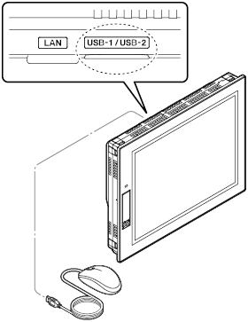
- Connect the dedicated monitor for TM-X and controller with a USB cable.

|
|
|
- Connect a mouse to the USB connector of the dedicated monitor for TM-X.
Connecting the Power to the Controller
|
|
Use wiring with a temperature rating of 80°C or more. |

|
|
|
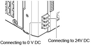
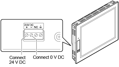
- Connect 24 V DC and 0 V to the power terminal.
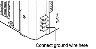
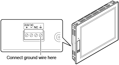
- Connect the ground wire to the grounding terminal.

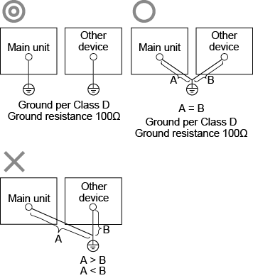
- Ground each device separately.
- Use a Class D ground.
- Keep ground resistance to 100Ω or less.
- Keep the ground wire as short as possible.
- If it is not possible to ground each device separately, ground them together. However, make sure that the electrical cables are the same length.
Connecting the Power to the Dedicated monitor for TM-X
- Connect 24 V DC and 0 V to the power terminal.
- Connect the ground wire to the grounding terminal.
|
|
|

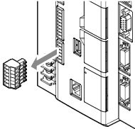
How to use the terminal block
This section explains how to use the terminal block.
|
|
Use wiring with a temperature rating of 80 °C or more. |
|
|
|

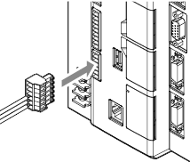
- Remove the connector terminal block from the controller.
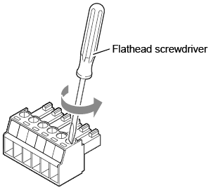
- Loosen the screw of the connector terminal block using a flat head screwdriver.
- After stripping the insulating sheath 7 mm, insert the wires and then tighten the screws.
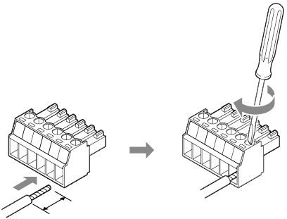
|
|
Pull each lead wire gently to confirm that it is properly secured. |
- After connecting all the necessary wires, securely insert the connector terminal block into the I/O connector as far as it will go.